
Active Sludge Purifiers
Active Sludge Purifiers OM12-150
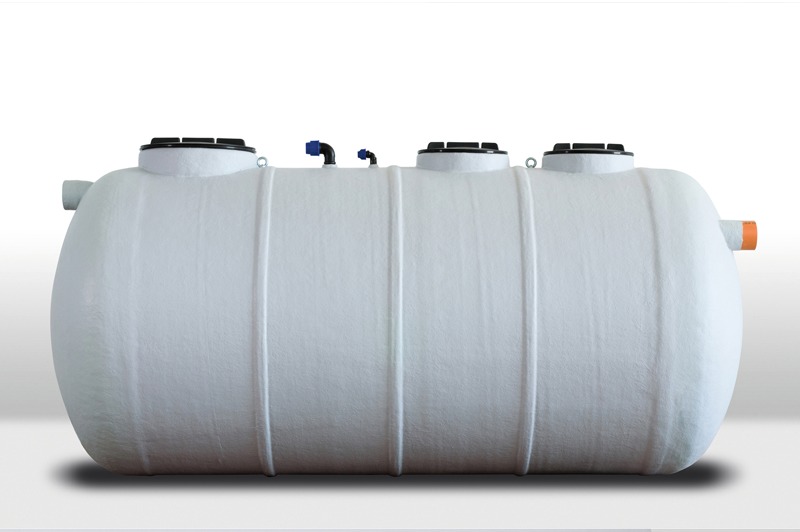
The Active Sludge OM12-150 purifiers made by Eco Depurazione entirely in GRP (Glass-Reinforced Polyester) are monobloc horizontal axis cylindrical structures sized for the primary treatment of waste waters coming from civil discharges or integrated waste characterised by a strong grade of mixed type organic substances based on the various uses for which the water is destined. Inside the structure opportune deflector baffles in GRP are inserted for the purpose of sub-dividing the equipment itself into two distinct areas – oxidation and sedimentation.
Operation
In the oxidation section the organic substances are metabolised by action on the aerobic bacterial flora, favoured by an intense aeration via opportune fine bubble air diffusers connected with PVC piping to a side channel blower. The waste water coming from the oxidation section arrives at the sedimentation section where the sludge flakes are separated from the water with opportune retention times in a settling zone adjacent to the oxidation catchment area which it is in communication with via two opportunely interposed baffles.
In this phase the treated water is separated from the sludge which is partly recirculated into the oxidation section via an air-lift in order to maintain the aforementioned aerobic conditions. The clarified water in turn is conveyed to the disposal after passage into an opportune well which allows drawing for checks on the water required by law. The treatment allows for a strong decrease of the BOD5 which influences the sludge with significant mineralisation.
Item Specifications
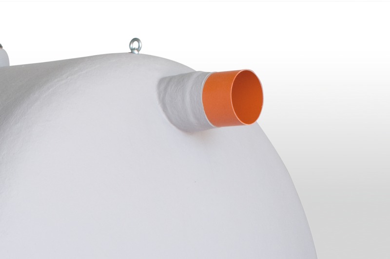
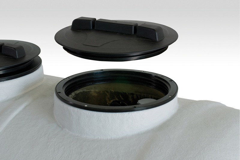
Supply of an active sludge OM12-150 purification system made entirely from GRP (Glass-Reinforced Polyester) comprised of a monobloc horizontal axis cylindrical structure sub-divided into two different sections: oxidation, for removal of the organic substances, and sedimentation, for the separation of the sludge flakes from the water; complete with waste water intake and output gates, upper compartment inspection manholes, fine air bubble diffusers, side channel blowers and connection piping. The system is sized to guarantee the limits established for civil waste waters in accordance with Legislative Decree No. 152/06 and subsequent modifications and integrations.
Dimensions
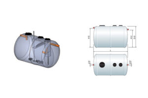
| ARTICOLO | AB/EQ Max | Volume Mc | Vasca di ossidazione | Soffiante | ||||
| ØD1 | L | HE | HU | Nr. | Kw | |||
| OM12 | 12 | 2,40 | 1500 | 2000 | 1300 | 1250 | 1 | 0,37 |
| OM15 | 15 | 3,00 | 1500 | 2150 | 1300 | 1250 | 1 | 0,37 |
| OM20 | 20 | 4,00 | 1500 | 2850 | 1300 | 1250 | 1 | 0,75 |
| OM25 | 26 | 5,00 | 1500 | 3400 | 1300 | 1250 | 1 | 075 |
| OM30 | 30 | 6,00 | 1800 | 3000 | 1600 | 1550 | 1 | 1,1 |
| OM35 | 35 | 7,00 | 1800 | 3300 | 1600 | 1550 | 1 | 1,1 |
| OM40 | 40 | 8,00 | 1800 | 3700 | 1600 | 1550 | 1 | 1,1 |
| OM50 | 50 | 10,00 | 2100 | 3500 | 1900 | 1850 | 1 | 2,2 |
| OM50-B | 50 | 10,00 | 1800 | 4600 | 1600 | 1550 | 1 | 1,5 |
| OM60 | 60 | 1200 | 2100 | 4150 | 1900 | 1850 | 1 | 2,2 |
| OM70 | 70 | 14,00 | 2100 | 4700 | 1900 | 1850 | 1 | 2,2 |
| OM80 | 80 | 16,00 | 2100 | 5250 | 1900 | 1850 | 1 | 2,2 |
| OM100 | 100 | 20,00 | 2100 | 6600 | 1900 | 1850 | 1 | 3,00 |
| OM150 | 150 | 30,00 | 2500 | 6900 | 2250 | 2200 | 1 | 3,00 |
Accessori
| ARTICOLO | DESCRIZIONE | U.M. |
| EM/LMS1/AC24 | Quadro elettrico di comando per soffiante Kw. 0.37 MF con uscita 24V allarme scatto termico | N.R. |
| EM/LMS1/AC24 | Quadro elettrico di comando per soffiante Kw. 0.75 MF con uscita 24V allarme scatto termico | N.R. |
| EM/LTS2/AC24 | Quadro elettrico di comando per soffiante Kw. 1.1 TF con uscita 24V allarme scatto termico | N.R. |
| EM/LTS2/AC24 | Quadro elettrico di comando per soffiante Kw. 1.5 TF con uscita 24V allarme scatto termico | N.R. |
| EM/LTS3/AC24 | Quadro elettrico di comando per soffiante Kw. 2.2 TF con uscita 24V allarme scatto termico | N.R. |
| EM/LTS3/AC24 | Quadro elettrico di comando per soffiante Kw. 3 TF con uscita 24V allarme scatto termico | N.R. |
DEPURATORE A FANGHI ATTIVI IN VETRORESINA ART. OM12-150
ARTICOLO | AB/EQ | Volume Mc | Dimensioni mm | Soffiante | ||||
ØD | L | HE | HU | N. | KW | |||
OM12 | Max 12 | 2,4 | 1500 | 2000 | 1300 | 1250 | 1 | 0,37 |
OM15 | Max 15 | 3,00 | 1500 | 2150 | 1300 | 1250 | 1 | 0,37 |
OM20 | Max 20 | 4,00 | 1500 | 2850 | 1300 | 1250 | 1 | 0,75 |
OM25 | Max 25 | 5,00 | 1500 | 3400 | 1300 | 1250 | 1 | 0,75 |
OM30 | Max 30 | 6,00 | 1800 | 3000 | 1600 | 1550 | 1 | 1,1 |
OM35 | Max 35 | 7,00 | 1800 | 3300 | 1600 | 1550 | 1 | 1,1 |
OM40 | Max 40 | 8,00 | 1800 | 3700 | 1600 | 1550 | 1 | 1,1 |
OM50 | Max 50 | 10,00 | 2100 | 3500 | 1900 | 1850 | 1 | 2,2 |
OM50-B | Max 50 | 10,00 | 1800 | 4600 | 1600 | 1550 | 1 | 1,5 |
OM60 | Max 60 | 12,00 | 2100 | 4150 | 1900 | 1850 | 1 | 2,2 |
OM70 | Max 70 | 14,00 | 2100 | 4700 | 1900 | 1850 | 1 | 2,2 |
OM80 | Max 80 | 16,00 | 2100 | 5250 | 1900 | 1850 | 1 | 2,2 |
OM100 | Max 100 | 20,00 | 2100 | 6600 | 1900 | 1850 | 1 | 3,00 |
OM150 | Max 150 | 30,00 | 2500 | 6900 | 2250 | 2200 | 1 | 3,00 |
QUADRO ELETTRICO:
ARTICOLO | Descrizione |
EM/LMS1/AC24 | Quadro elettrico di comando per soffiante KW. 0.37con usc. allarme.24V |
EM/LMS1/AC24 | Quadro elettrico di comando per soffiante KW. 0.75 con usc.allarme 24V |
EM/LTS2/AC24 | Quadro elettrico di comando per soffiante KW. 1.1 con usc.allarme 24V |
EM/LTS2/AC24 | Quadro elettrico di comando per soffiante KW. 1.5 con usc.allarme 24V |
EM/LTS3/AC24 | Quadro elettrico di comando per soffiante KW. 2.2 con usc.allarme 24V |
EM/LTS3/AC24 | Quadro elettrico di comando per soffiante KW. 3.00 con usc.allarme 24V |
Data sheet
Materials used
- GRP (Glass-Reinforced Polyester) STRUCTURE
- PVC PIPING –
- PP (Polypropylene) MANHOLES
Standards
UNI EN 12566-3:2005 – Legislative Decree 152/06 S.M.I.
further information?
Contact us for more information at the following addresses or fill out the form below:
- Tel. [+39] 06.92.58.722
- Fax. [+39] 06.92.58.722
- info@ecodepurazione.com
Eco Depurazione
Italian company specialized in the production of fiberglass products for applications in the sector of wastewater purification plants, for the storage and treatment of fluids in the civil and industrial sectors.
Products
- Purification
- Tanks
- Nautical
- Polyethylene products
Contacts
- Registered office: via Nairobi, 40 - 00144 Roma
- Operational Headquarters: Via Spaccasassi, 1 Aprilia (LT)
- Tel. [+39] 06.92.58.722
- Fax. [+39] 06.92.58.722
- info@ecodepurazione.com
- info@ecodepurazione.it
- P.IVA 02061210593
Cookie Policy | Privacy Policy | Gestione dati
Gestisci Consenso Cookie
Per fornire le migliori esperienze, utilizziamo tecnologie come i cookie per memorizzare e/o accedere alle informazioni del dispositivo. Il consenso a queste tecnologie ci permetterà di elaborare dati come il comportamento di navigazione o ID unici su questo sito. Non acconsentire o ritirare il consenso può influire negativamente su alcune caratteristiche e funzioni.
Funzionale Always active
L'archiviazione tecnica o l'accesso sono strettamente necessari al fine legittimo di consentire l'uso di un servizio specifico esplicitamente richiesto dall'abbonato o dall'utente, o al solo scopo di effettuare la trasmissione di una comunicazione su una rete di comunicazione elettronica.
Preferenze
L'archiviazione tecnica o l'accesso sono necessari per lo scopo legittimo di memorizzare le preferenze che non sono richieste dall'abbonato o dall'utente.
Statistiche
L'archiviazione tecnica o l'accesso che viene utilizzato esclusivamente per scopi statistici.
L'archiviazione tecnica o l'accesso che viene utilizzato esclusivamente per scopi statistici anonimi. Senza un mandato di comparizione, una conformità volontaria da parte del vostro Fornitore di Servizi Internet, o ulteriori registrazioni da parte di terzi, le informazioni memorizzate o recuperate per questo scopo da sole non possono di solito essere utilizzate per l'identificazione.
Marketing
L'archiviazione tecnica o l'accesso sono necessari per creare profili di utenti per inviare pubblicità, o per tracciare l'utente su un sito web o su diversi siti web per scopi di marketing simili.